


INSTALLATION-CONFIGURATION
SECTION 200-096-204
FEBRUARY1991
be needed. The three CO linescan be handled
by one PCOU PCB.
The two modems are configured in a system
modem pool and if no dedicated CO lines are
provided, then one standard telephone
(PSTWPESU) station port is required for
each; therefore a PESU or PSTU would be
needed. The PCBs required for this configu-
ration are as follows:
Two PDKUs
One PCOU
One PESU or PSTU
A total of four universal stations needed.
A DK24 would suffice for this configura-
tion.
Example
~-TWO tenants in one building require,
on a combined basis, 13 CO lines, 23 electronic
telephones, eight standard DTMF telephones, a
FAX machine, four DSS consoles, remote main-
tenance, and an interface to their alarm system.
l
The PIOUS PCB can provide remote mainte-
nance for their telephone system and also act
as an alarm sensor to alert employees through
electronictelephones. An IMDU subassembly
on the PIOUS fulfills the need of a modem for
remote maintenance, but does not deduct
from the universal slot count. The four DSS
consoles need to be interfaced as eight elec-
tronic telephones in addition to the 23 elec-
tronic telephones (resulting in a total of 31
equivalent electronic telephones). Therefore,
a total of four PEKU PCBs would be installed,
which would each have a DSS console con-
nected. One FAX machine in addition to eight
standard telephones means that one PSTU
and one PESU PCB are needed. Because
DTMF is coming into the system, a CRCU
needs to be installed, but does notdeductfrom
the universal slots available. The total PCB
requirement (in addition to common equip-
ment) is as follows:
Four PCOU PCBs
Four PEKU PCBs
One PSTU PCB
One PESU PCB
One PIOUS PCB
One IMDU subassembly
One CRCU subassembly
l
A total of 11 universal slots are required, so
a STRATA DK96 can fill the bill.
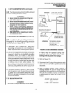
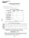
2.30 Door Phones
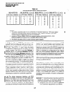
2.31 Up to 12 door phones (MDFB) can be accom-
modated by either a DK24, DK56, or a DK96
equipped with a PCTU (1,2, or 3). However, DK24
equipped with PCTUSI can support only nine door
phones. A door phone control (HDCB) interface
unit is required for every three door phones. Each
HDCB is interfaced to a STRATA DKsystem via the
PEKU or PESU PCB, and must occupy circuit 5 on
either PCB. For system configuration, each HDCB
must be considered equivalent to an electronic
telephone as far as consuming station capacity.
Table 4-E provides more details regarding HDCB
configuration.
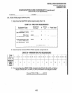
2.40 E & M TIE Lines
2.41 Each PEMU PCB provides interface to four
TIE lines. Up to four TIE lines can be accommo-
dated by DK24, up to eight by DK56, and up to
twelve by DK96. TIE lines (PEMU) are the same as
CO lines (PCOU), when considering the maximum
total outside lines in a system. The maximum lines
per system are 16 for DK24,24 for DK56, and 36 for
DK96. In addition, each PEMU uses up station
ports so that the software-limited station capacity of
a system is reduced with every PEMU added. The
number of station ports consumed by the PEMU
depends on the type of PCTU used. If a PCTU (1,
2, or 3) is installed, the PEMU reduces the system
station capacity by four. If a PCTUSI is installed,
each PEMU reduces the station capacity by eight.
This is of concern only in a DK24 system that
requires more than 16 stations. Each PEMU added
to a system uses up one universal slot.
NOTE:
DK24’s limit of four TIE lines (one PEMU) is
due to power supply capacity. Do not exceed
this limit.
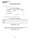
2.50 Off-hook Call Announce
2.51 If upgraded, each digital and electronic tele-
phone can receive off-hook call announce (OCA)
calls. In addition, PEKU PCBs supporting elec-
4-5