INSTALLATION-PCB
SECTION 200-096-206
FEBRUARY1991
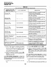
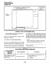
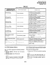
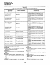
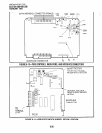
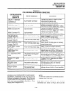
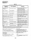
TABLE 6-E
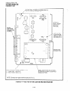
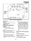
PCOUCONTROLS,INOICATORS,ANDlNTERFACECONNECTORS
CONTROL/INDICATOR/
CONNECTOR
(Figure 6-8)
TYPE OF COMPONENT
DESCRIPTION
CO Line Circuit 1
Indicator CD1 12
Red LED
Lights to indicate CO line circuit 1 is in
operation (NOTE: CO line indicator will
not light unless PCOU is connected to
a CO).
CO Line Circuit 2
Indicator CD21 2
Red LED
Lights to indicate CO line circuit 2 is in
operation (NOTE: CO line indicator will
not light unless PCOU is connected to
a CO).
CO Line Circuit 3
Indicator CD31 2
Red LED
Lights to indicate CO line circuit 3 is in
operation (NOTE: CO line indicator will
not light unless PCOU is connected to
a CO).
CO Line Circuit 4
Indicator CD41 2
Red LED
Lights to indicate CO line circuit 4 is in
operation (NOTE: CO line indicator will
not light unless PCOU is connected to
a CO).
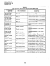
Jl Connector
Modular connector
Interface connector for CO line circuits
1 and 2.
J2 Connector
Modular connector
Interface connector for CO line circuits
3 and 4.
PAD Switch SW1 01
Two-position slide
Enables -3dB signal level drop for CO line
circuit 1.
PAD Switch SW201
Two-position slide
Enables -3dB signal level drop for CO line
circuit 2.
PAD Switch SW301
Two-position slide
Enables -3dB signal level drop for CO line
circuit 3.
PAD Switch SW401
Two-position slide
Enables -3dB signal level drop for CO line
circuit 4.
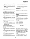
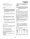
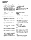
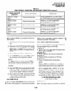
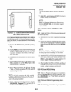
through programming, for the PCOU:
l
Specify code 11 for the applicable PCB slots
Program 03
where each PCOU is installed.
Program 1 O-l
l
Allows/denies two-CO Line Conference and
DISA.
Program 15
l
Assigns DTMF/DP Dialing, Tenant Service, DISA,
and a number of additional attributes to each CO
line.
Program 16
l
Assigns CO lines to groups 81 N 89, and dial 9
l
Assigns stations access to CO lines (incoming
group.
and outgoing access).
Program 41
l
Assigns stations access to CO lines (outgoing
Program 40
only).
Program 42-0, l-8
l
Assigns behind PBXCENTREX operation to
each CO line.
I
Programs 45 - 48
l
Defines Toll Restrictions for any CO line.
6-16


