


INSTALLATION-PCB
SECTION 200-096-206
FEBRUARY 1991
12 PCB INSTALLATION OVERVIEW
(RELEASE 3)
12.01
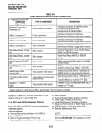
PCBslot installation considerationsdiscussed
in Paragraph 2 are the same with
Release 3,
except
for one change: with
Release
3, the PDKU PCB or
the PEKU PCB should be installed in slot I-previ-
ously only the PEKU was recommended. It does not
matter whether it’s the PEKU or the PDKU installed
in slot 1. However, it is recommended that they be the
first PCBs installed from left to right.
13 PDKU (RELEASE 3)
13.00 General
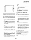
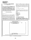
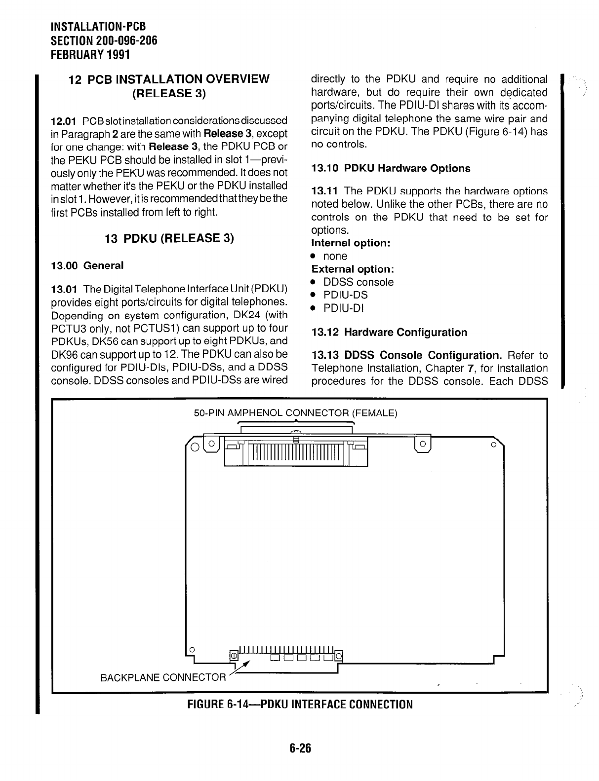
13.01 The Digital Telephone Interface Unit (PDKU)
provides eight ports/circuits for digital telephones.
Depending on system configuration, DK24 (with
PCTU3 only, not PCTUSI) can support up to four
PDKUs, DK56 can support up to eight PDKUs, and
DK96 can support up to 12. The PDKU can also be
configured for PDIU-Dls, PDIU-DSs, and a DDSS
console. DDSS consoles and PDIU-DSs are wired
directly to the PDKU and require no additional
hardware, but do require their own dedicated
ports/circuits. The PDIU-DI shares with its accom-
panying digital telephone the same wire pair and
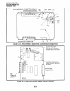
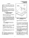
circuit on the PDKU. The PDKU (Figure 6-14) has
no controls.
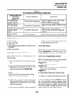
13.10 PDKU Hardware Options
13.11
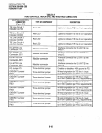
The PDKU supports the hardware options
noted below. Unlike the other PCBs, there are no
controls on the PDKU that need to be set for
options.
internal option:
l
none
External option:
l
DDSS console
. PDIU-DS
. PDIU-DI
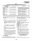
13.12 Hardware Configuration
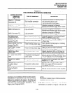
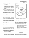
13.13 DDSS Console Configuration.
Refer to
Telephone Installation, Chapter 7, for installation
procedures for the DDSS console. Each DDSS
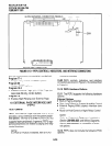
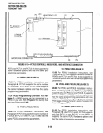
BACKPLANE
50-PIN AMPHENOL CONNECTOR (FEMALE)
, \
CONNECTOR
I
FIGURE 6-14-PDKU INTERFACE CONNECTION
6-26