


3 Beginning with a pair of labels marked 01, label each
cord at both ends with matching labels.
If the distance between a voice terminal location and
the control unit requires the use of extension cords,
label each end of the wiring run. Attach one label near
the plug to the voice terminal and the matching label
near the plug to the control unit.
4 Run cords from the voice terminal locations to the
control unit.
CAUTION:
Do not run cords inside air plenums or
ducts, along hot pipes, or across walkways. If you
use staples to attach cords to walls or baseboards,
be careful not to pierce the cords. If there are one
or more In-Range Out-of-Building voice terminals
to be installed, be sure to use two IROB protector
for each lROB voice terminal.
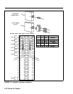
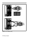
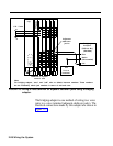
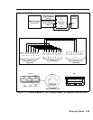
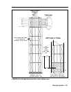
5 Thread each cord through the wire manager of the
control unit and up to the voice terminal jack with the
same number as the cord label, and plug it in. For
Release 3, refer to Form 1d System Form-Station
Planning; for Feature Module 1 or 2, refer to the
Master Planning Form to check the intercom number
assignments against the voice terminal jack locations.
Intercom 10, for example, is connected to the voice
terminal jack labeled 01 at the first jack location of the
first station module in the control unit.
2-26 Wiring the System