


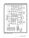
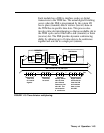


E&M SIGNALING
Most signaling systems, other than loop signaling, are
separate from the trunk equipment. They are normally
located between the trunk equipment and the line facility.
E&M signaling systems derive their name from the
historical designations of the signaling leads on
schematics covering these systems. By convention, the
"E" stands for ear and the "M" stands for mouth (rEceive
and transMit). The E&M lead signaling interface consists
of two leads between the switching equipment (central
office) and the signaling equipment (PBX). The “M lead
carries signals from the switching equipment to the
signaling equipment. The “E” lead carries return signals
from the signaling equipment to the switching equipment.
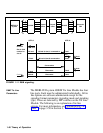
The E&M interface is designated as TL31M, and the 50-
pin connector is designated as RJ2GX. At the RJ2GX
interface, the PBX is the switching equipment side, and
the network side (toward the central office) is the
signaling equipment side. An example of E&M signaling
is shown in Figure 1-11.
Theory of Operation 1-45