


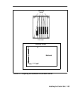
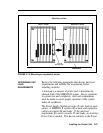
DETERMINING
MODULE SLOT
ASSIGNMENTS
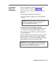
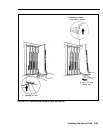
The slot assignments for modules in the basic and
expansion carriers are shown in Figure 2-14.
In order to function, a basic carrier must contain the
following:
●
A Power Supply Module in the leftmost slot
●
A Processor Module (equipped with a Feature Module)
in slot 0
CAUTION:
The Feature Module must be installed in
the Processor Module before installing the
Processor Module in the carrier.
●
An Analog Voice Terminal Module, either the
4-line 8-Analog Voice Terminal (408) Module or the
8-Analog Voice Terminal (008) Module, in slot 1
●
Line, tie line, or other modules can then be placed in
slots 2 through 5
The only requirement for an expansion carrier is that the
leftmost slot must contain the Power Supply Module.
Slots 6 through 11 can be filled with additional modules.
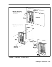
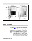
Install modules on the carrier from left to right.
CAUTION:
Do not leave empty slots between modules
in the carriers. The MERLIN II system will ignore
modules installed beyond an empty slot.
Installing the Control Unit 2-61