


6
7
8
9
10
11
12
13
14
15
Wrap the jacketed cable around the center post until
the colored wires extend over the two plastic caps.
Align the cable in one of the notches on the jack, and
attach the jack to the wall. One type of jack requires
screws, while another uses adhesive backing.
Remove the two plastic caps on the adapter (this
exposes the grooved connecting block), and set the
caps aside. They are used instep 10.
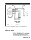
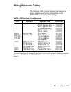
Insert the colored wires into the grooves from left to
right. See Table 2-3, “4-Pair Wiring” on page 2-46 for
color/pin assignments.
Align the caps over the grooved block and press them
down firmly until they snap into place.
Trim any colored wires protruding from the plastic
caps. When you‘re finished, none of the wires should
extend far enough beyond the plastic caps to touch
each other.
Put the cover on the adapter and tighten the screw.
Attach the blue wiring run label for this voice terminal
location (
❑
1) to the cover.
Connect the rest of the wiring runs from the jacks in
the jack field to the voice terminal locations in the
same way, making sure that both ends of each wiring
run are labeled identically.
When you have completed the wiring runs, use cable
ties and clips to bundle the cables at the jack field to
reduce cord clutter, and then close the doors on the
apparatus boxes.
You should now have a properly installed and labeled jack
field with building wiring connecting the voice terminal
locations to the control unit location.
2-40 Wiring the System