


●
Single-pair modular line cords.
You need one D2R
cord for each outside line. The cord must be long
enough to reach the network interface.
●
Green line-cord labels.
These labels are marked 01,
02, 03, etc. You need a matching pair for each line
cord.
●
Outside line numbering strips.
These labels are used
to number all the line jacks on the modules themselves.
You can have up to 56 outside line jacks with the
MERLIN II system. The numbering sequence is 01 to 56.
To connect the outside line wiring, follow these steps:
1 Review Form 1a, System Form-lncoming Lines for
Release 3, or the Master Planning Form for Feature
Modules 1 and 2, to determine each outside line
assignment on the control unit.
The outside line numbers are the telephone numbers
listed at the network interface or inside the left door of
the box in the jack field containing the jacks for your
outside lines.
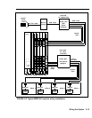
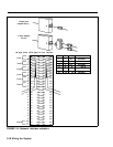
2 Number sequentially from 01 to 56 every outside line
jack on the modules using the outside line numbering
strips. Begin with the module in slot 1, numbering
from bottom to top and working from left to right
across the control unit (See Figure 2-2 on page 2-13
for the numbering sequence.)
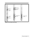
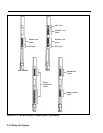
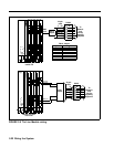
Refer to Figure 2-3 on pages 2-15 and 2-16 to identify
those modules that have line jacks and locate the
-
positions the line jacks occupy on those modules.
3 Connect the outside line jacks on the modules to the
network interface using D2R cords. Thread the wires
through the wire managers at the base of each module
as you connect the wires to the jacks. Label each end
of each cord with the outside line jack number to
which each is connected.
2-20 Wiring the System