


4 Write the telephone number assigned to each of the
TIE LINE MODULE
WIRING
line jacks next to the number for that line jack on the
outside line numbers label found on the inside of the
control unit’s front cover or on the inside of the left
door of the jack field box containing the outside lines.
WARNING:
National and local building codes specify
the type of cable required for telecommunication
wiring. For example, indoor wiring (DIW) cannot be
used inside or on top of air plenums or ducts, along hot
pipes; or across walkways. Consult your local
ordinances and regulations for proper cable selection.
If staples are used to attach the cords to walls or
baseboards, check that the cords have not been pierced.
Also, do not run Central Office lines from the network
interface to the control unit if the distance if greater
than 25 feet.
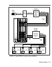
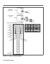
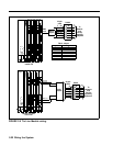
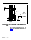
The interface from the Tie Line Module to the network
facility is provided through modular jacks. Each modular
jack provides an electrical interface to the network that
consists of six leads: T (pin 5) and R (pin 4) are for
outgoing analog transmission; T1 (pin 1) and R1 (pin 2)
are for incoming analog transmission; and E (pin 3) and M
(pin 6) are for signaling. Figure 2-5 shows how to connect
the Tie Line Module to the network interface.
WARNING:
The protected mode must be used
whenever the E&M leads extend out-of-building and
are not connected to the network interface. See pages
1-47 and 1-48.
Wiring the System 2-21