6 At the remote printer location, connect another 400B2
power adapter, as described in step 4. the output from
the 400B2 adapter is connected to the building wiring
and the input modular jack should be connected to the
ADU.
7 If the printer interface cable has a female connector,
connect the output modular jack of the power adapter
to a Z3A1 ADU. If the printer interface cable has a
male connector, connect the output modular jack of the
power adapter to a Z3A4 ADU.
8 Set the printer options for use with the Call Report
(SMDR) feature.
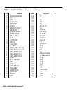
> If you have an AT&T 572 printer, set the
programming options on the printer according to
Table 2-10. Refer to the user’s guide supplied with
the printer for further information.
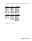
> If you have an AT&T 475/476 printer, set the DIP
switches on the printer according to Table 2-11.
Refer to the user’s guide supplied with the printer
for further information.
2-88 Installing the Control Unit


