


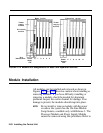
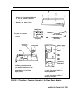
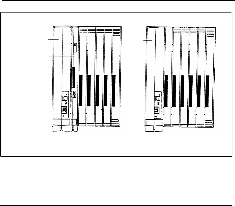
Power
supply
module
Processor
module
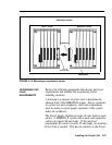
Slot
Basic Carrier
identification: Power O 1 2 3 4 5
Power
supply
module
Expansion carrier
Power 6 7 8 9 10 11
Supply
Supply
slot
slot
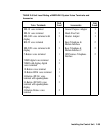
FIGURE 2-14 Module slot assignments on basic and expansion carriers.
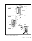
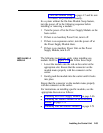
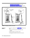
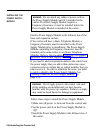
Module Installation
All modules can be installed and removed as shown in
Figures 2-15 and 2-16. Exercise caution when installing
or
removing modules. If you have difficulty installing or
removing a module, check the module for alignment
problems. Inspect the carrier channel for damage. If no
damage is present, the modules should snap into place.
NOTE:
Do not install or remove modules with the power
on unless the system has the On-Line Module
Swap feature, available only with Release 3. The
Processor Module and Power Supply Module
cannot be removed using this procedure. Refer to
2-62 Installing the Control Unit