


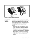
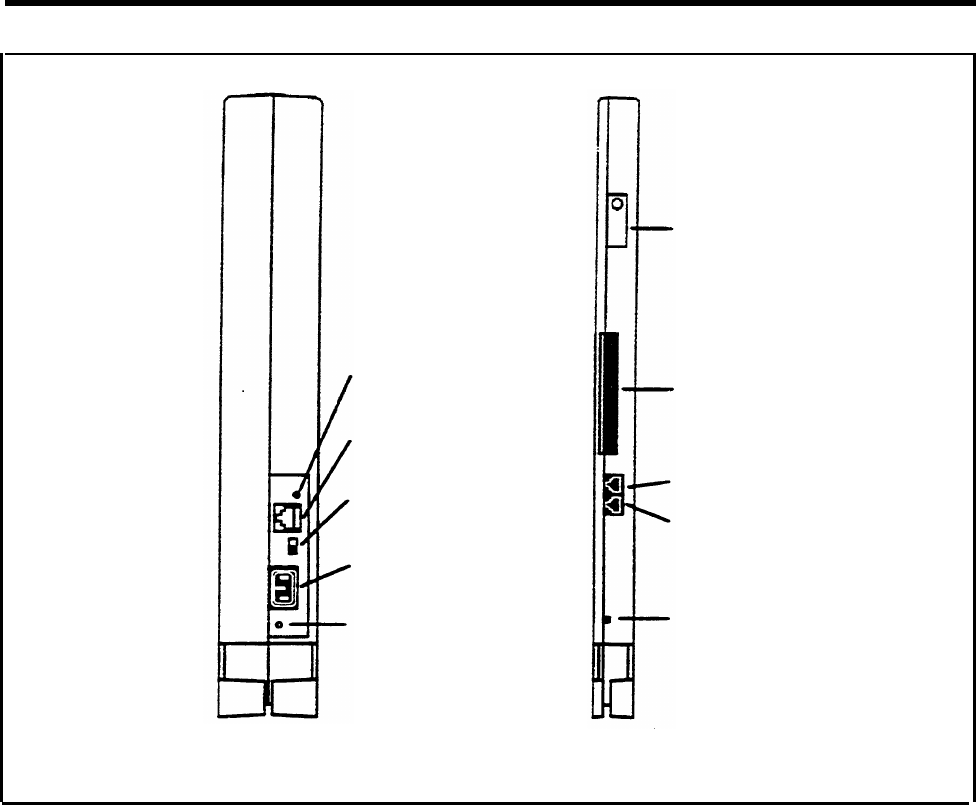
Power indicator
Auxiliary power
input jack
On/Off switch
Power
connector
Ground lug
Label
Diagnostic
96-pin connector
SMDR port
Application port
Warning light
Power supply module
Pr
ocessor module (517B7)
for Release 3
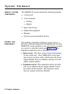
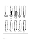
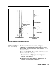
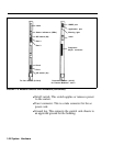
FIGURE 1-5 Module controls and indicators.
MODULE CONTROLS
The from panel controls, indicators, and special
AND INDICATORS
connectors (excluding line and station jacks) on control
unit modules are described below. Refer to Figure 1-5 to
locate these items.
Power Supply Module.
The controls and indicators for
this module are the following:
●
Power indicator. Its light goes on when power is
supplied to the module.
●
Auxiliary power input jack This jack provides the
interface for the Auxiliary Power Unit.
System Hardware 1-23