


2
3
4
5
6
7
8
9
10
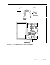
Remove Processor Module 517A7 from
S
1
O
t of the
Basic Carrier. See “Removing a Module” on page
2-64 for instructions.
Insert Feature Module 3 in the Release 3 Processor
Module (517B7). See “Installing the Feature Module
on the Processor Module” on page 2-73 for
instructions.
If needed, modify the Processor Module for square, or
key, operation. See “Modifying the 51737 Processor
Module for Square (Key) Operation” on page 2-78 for
instructions.
Insert the Release 3 Processor Module in slot 0 of the
Basic Carrier. See “Installing a Module” on page 2-63
for instructions.
Add line or station modules as needed. See “Installing
Line and Station Modules” on page 2-79 and/or see
“lnstalling a Basic Telephone Module” on page 2-81
for instructions.
If an Expansion Carrier has been added, insert the
Power Supply Module on that carrier in its slot.
See
“Installing the Power Supply Module” on page 2-66 for
instructions.
Consider unit load requirements to determine if any
Auxiliary Power Units are needed. See “Determining
Unit Load Requirements” on page 2-57 for information
about unit loads and their calculation.
Add Tie Line Modules as needed. See "Installing a
Tie Line Module” on page 2-81 for instructions.
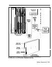
Connect any new CO lines as follows as appropriate:
> Connect new CO lines from the network interface
to the jack field if one has been used. Connect the
CO lines from the jack field to the proper jacks on
the line modules.
2-I 34 Upgrading an Existing System