


Connecting Voice
Terminal Wiring
Directly
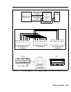
2 Wire the station jacks on the modules to the jack field
using D8W cords. Thread the wires through the wire
manager located at the base of each module as you
connect them to the station jacks. Label each end of
each wire with the intercom number to which it
connects. Remember, the intercom numbers do not
necessarily match the jack numbers. Intercom 10, for
example, is connected to station jack 01 on the first
station module of the control unit.
3 Record the end location of each intercom number on
the system directory label and put this label on the
inside of the front cover of the control unit.
Complete wiring instructions for data stations are found in
the separate document,
MERLIN II Communications
System Data Communications Guide.
To connect the voice terminal locations directly to the
control unit, perform the following steps:
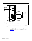
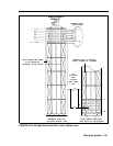
1 Number every station jack on the modules sequentially
from 01 through 120, using the station numbering
strips. Begin with the module in slot 1 and number
from bottom to top; then go on to the next module with
station jacks, working from left to right across the
control unit modules.
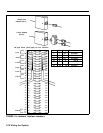
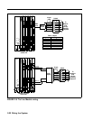
You may want to review Figure 2-3 on pages 2-15 and
2-16 to identify which modules have station jacks and
locate the positions of the station jacks on each
module.
2 In the system directory, fill in the voice terminal
location you have selected for each intercom number.
Wiring the System
2-25