


●
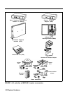
Power Supply Module.
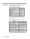
The Power Supply Module
converts 117 VAC line voltage to the following
outputs: +5 VDC, -5 VDC, and -48 VDC (tip/ring).
●
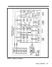
Processor Module.
The central processor complex
consists of a main board and the Feature Module. The
main board contains the 68000 microprocessor, RAM,
a real-time clock, interrupt circuitry, and port interface
to the modules through the I/O bus.
Communication between the Processor Module and
the port processors on the various modules occurs over
a parallel address/data bus. This structure allows
memory-mapped I/O with up to 1 megabyte per second
bandwidth.
●
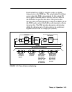
Input/Output Bus.
Included in the I/O bus are a 16-
bit address bus and an 8-bit data bus. The address bus
selects the module that receives instructions from the
68000 microprocessor. The microprocessor provides
instructions to the port processors and Digital Switch
Elements (DSEs) through the 8-bit data bus.
●
Time Division Multiplex Bus.
The Time Division
Multiplex bus (TDM) is a major part of the control
unit. It connects the DSEs to allow voice and data to
flow in and out of the MERLIN II system. The TDM
bus is parallel, 8 bits wide, and runs at 2.048 MHz.
Each TDM cycle has 256 time slots for voice, data,
tones, and clocks.
Voice signals on the TDM bus are encoded in “Mu-
Law 255” Pulse Code Modulation (PCM) format for
domestic use and “A-Law 100” for international
applications. See “Analog to Digital Signal
Processing” on page 1-40. Data signals are processed
according to Digital Communications Protocol (DCP).
●
408 or 008 Module.
A 408 Loop Start Line/ATL
Station Module or 008 module is required in slot 1 of
the basic carrier of the control unit. Note, however,
that the 008 module does not provide any outside lines
1-38 Theory of Operation