


Modifying the 517B7
If you have Processor Module 517B7, use the following
Processor Module for
inductions to modify it for square (key) operation:
Square (Key)
Operation
1
2
3
4
5
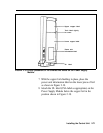
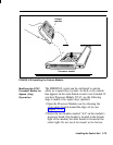
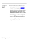
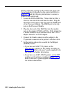
Before you insert the Feature Module, orient the
Processor Module case as shown in Figure 2-22. Do
not
open the Processor Module case.
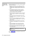
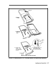
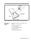
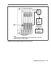
Notice the two headers marked “HD1” and “HD2” on
the module’s processor board. One header is located at
the bottom of the opening (HD2); the other header is
located at the top of the opening (HDl).
Do not touch
the header at the bottom.
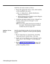
On the header close to the top of the opening, locate
the shunt (blue plug) attached to one of the pins.
Remove the shunt from the single header pin, then
reinsert it so that it covers both pins on the header.
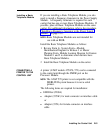
Locate the
KF
(Key Function) label that came with the
wall mount carrier label kit and affix it to the wire
manager at the base of the module.
2-78 Installing the Control Unit