


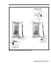
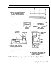
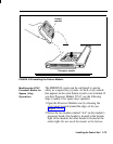
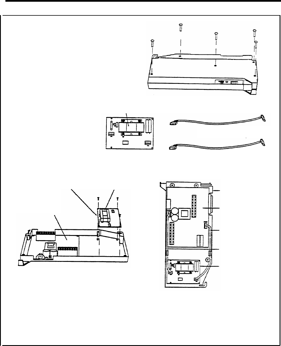
1. Position the Power Supply Module
so that the recessed holes ate
facing up. Remove five screws.
2. Separate the module halves.
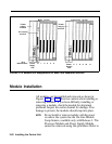
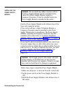
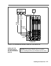
3. Locate the Frequency
Generator and the two
cables.
Frequency
Generate;
Transformer
Long cable
(4-pin connectors)
Frequency
Short cable
Generator
(3-pin connectors)
Transformer
Main
board
Frequency
Generator
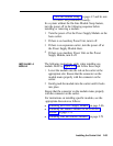
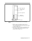
4. Using four screws, mount the
Frequency Generator on the
Power Supply Module. lnstall
it so that the transformer on the
Frequency Generator is close to
the main board of the Power
Supply Module.
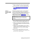
5.
6.
Power Supply
Module
Main circuit
board
4-pin
cable
3-pin
cable
Connect 3-pin cable between P101
on main circuit board and P1 on
Frequency Generator.
Connect 4-pin cabIe between P202
on main circuit board and P2 on
Frequency Generator.
FIGURE 2-17 installing a Frequency Generator in the Power Supply Module.
Installing the Control Unit 2-69