


1
2
3
4
5
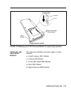
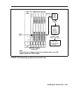
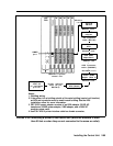
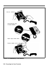
Locate the Z200A EMI filter. Notice that the filter is
closer to one end of the cord than the other. Plug the
end of the cord closest to the filter into the SMDR port
of the Processor Module. The SMDR port is the top
port on the Processor Module.
Plug the other end of the EMI filter into the modular
jack on the adapter (355AF or 355A).
Connect the female connector on the 355AF adapter to
one end of the EIA crossover cable. Connect the other
end of the cable to the 25-pin male connector of the
Z3AI ADU.
Connect the modular jack marked “telephone” on the
ADU to one of the input modular jacks on the 400B2
power adapter. The 2012D ac transformer is connected
to the other input modular jack of the power adapter
via a 248B adapter and a D6AP-87 power cord.
Plug the output modular jack from the 400B2 adapter
into the ADU crossover cable (D8AM-87). Connect
the output of the D8AM-87 to the building wiring.
WARNING:
If the printer is in a building outside of
the main (control unit location) building, an ADU
and an additional protector must be installed in each
building. The ADUs and protectors provide both
the control unit and the printer additional protection
against exposure to lightning, inadvertent contact
with power lines, and power currents induced by
nearby power lines. See the ADU installation notes
for more information.
Installing the Control Unit 2-87