


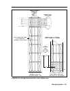

CONSTRUCTING A
JACK FIELD FOR
VOICE TERMINAL
WIRING
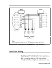
Jack Field
Construction
Requirements
You may also decide to connect the outside wiring
directly from the network interface to the control unit and
the voice terminal wires directly from the voice terminal
locations to the control unit. If the installation is simple or
other factors determine that direct wiring is best for all
connections, you may skip these wiring instructions.
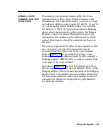
Although you can connect the voice terminals to the
control unit in any of several different ways, the method
described here greatly simplifies certain aspects of system
administration. This method calls for wiring runs that
terminate in modular wall jacks at the voice terminal
locations and in modular jacks in a jack field at the control
unit location. Modular jumper cords then connect the
jacks in the jack field to the appropriate jacks in the
control unit.
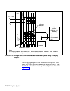
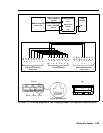
In order to construct a jack field and connect the voice
terminals to it, you need the following:
●
Floor plan.
This plan should show the route of the
wiring runs from the control unit location to the voice
terminal locations. If you don’t have one, draw one
now.
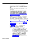
●
4-Pair station adapters
You need as many 4-pair
modular jack terminated adapters as you have voice
terminals in the system. Some examples are the
following:
> The Z600A modjack-to-modjack adapter-an in-
line connector for modular cords allowing for a
jack-to-jack arrangement.
> The Z601A cutdown-to-modjack adapter-for
connecting cutdown cable to modular jacks.
> The Z602A adapter—for connecting up to six
modular cords to a connectorized 25-pair cable.
Wiring the System 2-35