


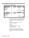

5
6
7
8
9
10
11
12
13
14
15
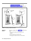
CAUTION:
Be sure to follow proper electrostatic
discharge precautions. Refer to “Static Discharge
Problems” on page 2-9.
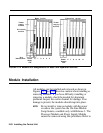
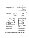
With the Power Supply Module out of the carrier and
on its left side, remove the five screws.
Carefully turn the module over on its right side and
remove the left half of its housing.
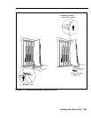
Position the remaining half of the module so that the
connector at the back of the module is facing you.
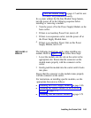
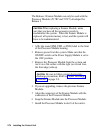
Position the Frequency Generator so that its screw
holes are aligned with the screw posts on the Power
Supply Module.
Attach the Frequency Generator to the Power Supply
Module using four screws.
.
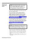
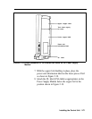
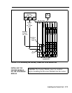
Locate the cable that has two 3-pin connectors.
Connect one end of the cable to the header labeled
P101 on the Power Supply Circuit Board. Connect the
other end of this cable to the header labeled P1 on the
Frequency Generator.
Locate the cable that has two 4-pin connectors.
Connect one end of the cable to the header labeled
P202 on the Power Supply Circuit Board. Connect the
other end of the cable to the header labeled P2 on the
Frequency Generator.
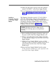
Replace the left half of the module housing. Make
sure that the faceplate is positioned correctly.
Turn the module over and replace the five screws
removed in step 5.
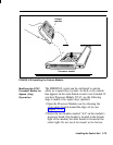
Affix the modification label to the wire manager on the
front end of the Power Supply Module.
Install the Power Supply Module in the carrier.
2-68 Installing the Control Unit