


Outside Line Wiring
PREPARING THE
NETWORK
INTERFACE
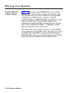
The local telephone company provides the telephone
numbers for outside lines, as well as an installed network
interface that may consist of 1-Line adapters (RJ11-type),
2-line adapters (RJ14-type), or 25-line (50-pin, RJ21-type)
connectors.
You can connect the outside lines from the network
interface connector to the control unit using D2R cords.
The method used to connect the outside lines to the
control unit depends on the type of network interface as
follows:
●
1-line adapter (RJ1l-type). This adapter allows one
connector for each outside line.
> Label each jack with the telephone number.
● 2-line adapter (RJ14-type). This adapter connects
two outside lines per jack.
> Label each jack with the telephone numbers of its
two outside lines.
>
Plug a 2-line adapter (267C-type) into each jack.
●
50-pin connector (RJ21-type). This connector carries
up to 25 lines.
>
Label the interface with the numbers for the
outside lines.
>
To extend the network interface to the jack field,
refer to the instructions in “Jack Field Wiring” on
page 2-33.
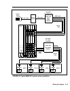
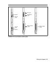
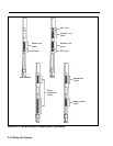
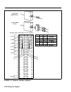
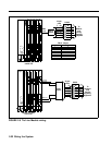
Refer to Figure 2-4 for examples of network interfaces and
adapters.
Wiring the System 2-17