


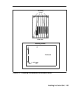
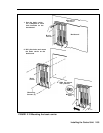

To mount the basic carrier to the backboard, refer to
Figure 2-12 and follow these steps:
1
2
3
4
5
Use the basic carrier as a template to mark the hole
locations on the mounting surface.
Position the carrier on the backboard and check that all
measurements are correct. The vertical distance
between mounting holes should measure 18 inches.
The horizontal distance should measure 9 7/26 inches.
Use a l/8-inch drill bit to drill a pilot hole in the center
of each of the four marked mounting hole locations.
Insert the screws provided but leave enough room
between the screw head and the backboard surface for
the mounting bosses on the carrier.
Mount the carrier on the screws through the holes in
the mounting bosses. Slide the carrier to the left along
the boss slots and tighten the screws.
2-54 Installing the Control Unit