


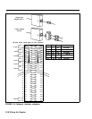
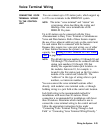

Refer to “Jack Field Wiring” on page 2-33 for instructions
on how to construct a jack field. You need the following
items to complete the connections:
●
●
●
●
●
System directory label.
Use this label to record the
end locations of each intercom number in the system.
Blue station-cord labels.
These labels come in pairs
with the basic and expansion carrier and are used to
identify cable runs. The first sheet of labels is
numbered 01 through 69 and is shipped with the basic
carrier. The second sheet is numbered 70 through 120
and 700-759. This sheet is packed with the expansion
carrier. You should have a matched pair of labels for
each line cord.
4-Pair modular jumper cords.
These cords are for
jack field connections. You should have one cord for
each voice terminal in your system.
System Labels.
These labels, used to number jacks,
are shipped with the feature module. They are
numbered 1 through 56 for lines and 01 through 120
for stations.
Line Cable Numbering Labels.
These green labels
come in pairs and are numbered 01 through 56.
Connecting Voice
To connect the station wiring through a jack field, perform
Terminal Wiring
the following steps:
Through a Jack Field
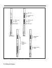
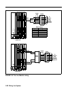
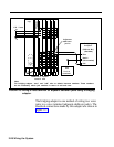
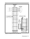
1 Number every station jack on the modules sequentially
from 01 through 120, using the station numbering
strips. Begin with the module in slot 1, and number
from bottom to top, then continue from left to right
across the control unit (See Figure 2-2 on page 2-13.)
You may want to review Figure 2-3 on pages 2-15 and
2-16 to identify which modules have station jacks and
locate the positions of the station jacks on each
module.
2-24 Wiring the System