


6
7
8
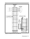
Insert and punch down (connect the wires of the
spooled cable into the cutdown section of the adapter
next
to
the label for wiring run 1 in the jack field (the
top jack in the box labeled
❑
1-6). If necessary, trim
the ends of the wires with a pair of scissors or diagonal
pliers.
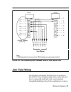
Run the other end of the cable to the voice terminal
location where wiring run number 1 ends. Use cable
clips and/or staples to attach the cable along walls,
baseboards, and moldings.
Run the rest of the cables consecutively from the
connections in the jack field to the corresponding
voice terminal locations.
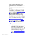
Follow this
procedure to terminate wiring runs in modular
wall jacks.
1
2
3
4
5
At the voice terminal location for wiring run number 1,
mark the place on the wall where you want to put the
modular wal1 jack.
Trim the excess cable, leaving enough so that about 4
inches extend beyond the outline of the modular jack
you drew on the wall.
Loosen the screw that holds the cover of the wall jack
in place, remove the cover, and set the cover and screw
aside.
Using the cable termination tool, remove about 2
inches of the cable’s jacket. This exposes the color-
coded twisted pairs of wires inside the jacket.
Thread the cable from the bottom of the jack up
through the center until the exposed wires and 1/4 inch
of the cable’s jacket come through next to the center
post on the jack.
Wiring the System 2-39