


Installing the Control Unit
Procedure
See the Control Unit Diagram on the back of System Form 1, System Planning,
to determine the order of modules.
Once you have installed the power supply and the processor in the basic
carrier, use the remaining slots for the modules as follows:
■ Basic carrier: slots 1 through 5
■ First expansion carrier: slots 6 through 11
■ Second expansion carrier: slots 12 through 17
Follow this procedure to install the modules, starting from Slot 1 (the first open
slot next to the processor).
1.
2.
3.
4.
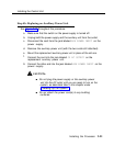
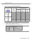
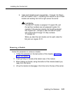
For each 400EM module trunk jack (numbered as ports 1 through 4 in
Figure 2-16, check the System Planning Form 3d (Outside Trunks—
Tie). If the
E&M Signal
column indicates
1C
or
5
for a particular
logical ID, set the DIP switches on the front of the 400EM module, as
shown in Table 2-4 and Figure 2-14.
NOTE:
The default E&M signal,
1S,
does not require any adjustments in
the DIP switches.
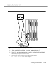
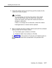
Remove the protective cover from each module’s gold-finger
connector.
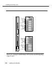
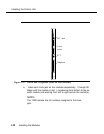
Lower the module onto the rod on the top of the carrier in the
appropriate slot as shown in Figure 2-14.
Be sure that the connector on the module mates properly with the
connector on the carrier.
2-56
Installing the Modules