


Connecting the Control Unit to the Network Interface
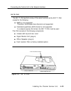
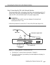
Step 3: Connecting the CSU to the Network Interface
The terminal block (TB1) on the back of the CSU is the connecting point for T1
service lines, fault wires, and Ioopback wires. Also, if a local power supply is
used, the TB1 is the termination spot for the power supply wires.
WARNING:
Voltages as high as 260 V can occur between the transmit and
receive pairs of the T1 line.
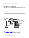
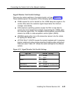
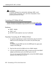
Follow this procedure to connect the T1 lines to the CSU (see Figure 4-9):
D8W Cord
Local power supply leads
T1
Trunks
Fault
Pair
TB 1 2 3 4 5 6 7 8 9
10 11 12 13 14 15 16 17
J1
T1 R1 T R
DC Loopback pair
To Network
Figure 4-9. Connecting the T1 Lines to the CSU
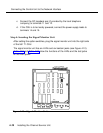
a. Connect the T1 service lines to terminals 1 through 5.
b. Connect the fault pair (if provided by the local telephone company) to
terminals 8 and 9.
Installing the Channel Service Unit
4-37