


Installing Telephones and Adjuncts
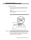
c. Lower the cover to the right and press firmly to lock the tabs in
place. Both tabs must be secure.
d. Replace and tighten the screw you removed earlier.
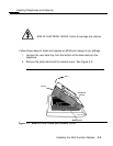
7. Replace the desk stand
NOTE:
If you are wall mounting an MLX-10 or MLX-10D telephone, do not
replace the desk stand. Go to Step 8.
and the user card tray.
a. The desk stand has two height adjustments. Insert the tab at the
bottom of the stand in either the low or high position.
b. Insert the tab at the top of the stand into the corresponding slot
on the desk telephone. To readjust the stand, see the
instructions on the bottom of the card tray.
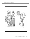
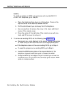
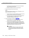
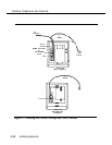
8. Power up the telephone as follows (see Figure 3-6):
a. Plug the D8W cord from the telephone into the 8-conductor
(large) modular jack of the 400B or 400B2 adapter.
b. Connect one end of the D6AP cord to the 2-conductor (small)
modular jack on the 400B or 400B2 adapter, and plug the other
end into the modular jack of the KS22911-L2 power supply. The
total length of the cords connecting the power supply to the MLX
telephone must be less than or equal to 50 ft (15
m).
CAUTION:
Do not plug the D6AP cord into the 8 conductor (large)
modular jack on the 400B or 400B2 adapter; doing so
can cause electrical damage to the control unit and the
telephone.
3-10
Installing the Multi-Function Module