


Installing Telephones and Adjuncts
8.
9.
10.
11.
12.
13.
14.
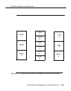
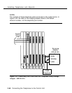
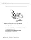
As shown on the template, mount the wire troughs on column 2 after all
the field-terminated blocks have been wired.
Mount the D-rings between the columns as needed to route the patch
cords.
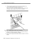
Plug one end of a D8W cord into the proper control unit module
telephone jack and the other end into the corresponding jack on the
termination block in column 1 or column 3.
Repeat for all the D8W cords.
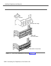
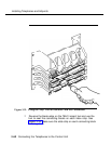
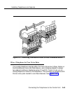
Route the D8W cords through the wire trough above the termination
block. See Figure 3-26 and Figure 3-27.
NOTE:
Each kit has extra D-rings and wire troughs. Use them as needed
to route the cords.
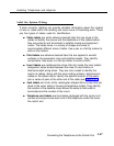
Label the termination and field-terminated blocks. See “Label the
System Wiring” later in this chapter). Write the appropriate information
(such as extension numbers and users’ names) on the strip labels
provided and snap the designation strips into place.
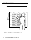
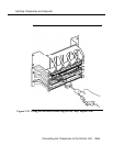
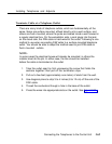
Use the 110P8A5B patch cords to connect termination blocks to
field-terminated blocks. See Figure 3-33. Properly route the patch
cords through the wire troughs and D-rings.
3-62 Connecting the Telephones to the Control Unit