


Connecting the Control Unit to the Network Interface
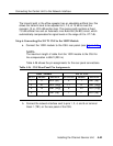
c. Connect the DC Ioopback pair (if provided by the local telephone
company) to terminals 11 and 12.
d. If the CSU is to be locally powered, connect the power supply leads to
terminals 14 and 15.
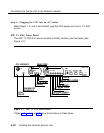
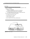
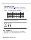
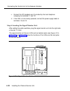
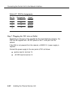
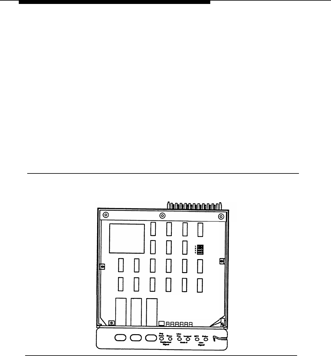
Step 4: Inserting the Signal Monitor Unit
After setting the option switches, plug the signal monitor unit into the right side
of the 551 T1 CSU.
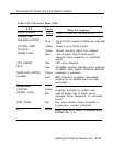
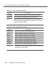
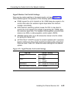
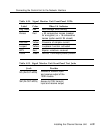
The signal monitor unit has six LEDs and six bantam jacks (see Figure 4-10).
Table 4-24 and Table 4-25 show the functions of the LEDs and the test jacks
on the front panel.
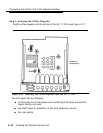
21-PIN I/O CONNECTOR
OPTIONS
SWITCH (DIP)
LEDs
Signal Monitor Unit
EQ EQ SM SM SM SM
IN OUT MON IN OUT MON
Figure 4-10. Signal Monitor Unit
4-38
Installing the Channel Service Unit