


Connecting the Control Unit to the Network Interface
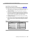
Signal Monitor Unit Switch Settings
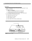
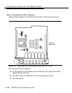
There are four option switches in the signal monitor unit (see Figure 4-10).
These switches govern the operation of the following options:
■
■
■
■
ONES causes the unit to transmit an ALL ONES keep-alive signal to
central office when the customer signal drops below the minimum
average ones-density.
ESS (electronic switching system) causes the CSU to loop back its
the
receive line to its transmit line (instead of generating ALL ONES) when
the customer signal fails. The Ioopback framing pattern prevents false
alarms at an ESS or a data acquisition control system (DACS).
ZEROES selects either 16 or 50 consecutive zeroes to be the criteria
for lighting the Zeroes LED.
ACTIVE FAULT LOCATE causes the remote Ioopback path to preserve
bipolar violations to allow single-ended fault locating when active fault
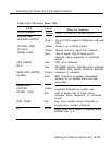
filters are used. Table 4-21 shows the switch settings for the different
options.
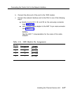
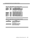
Figure 4-21. Signal Monitor Unit Switch Settings
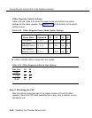
Option Switch Setting
ONES
#1
— closed
#2
— open
ESS
#1
— open
#2
— closed
ZEROES
#3 — closed for 16-zero limit
ACTIVE FAULT LOCATE #4 — closed
Installing the Channel Service Unit
4-35