


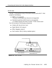
Connecting the Control Unit to the Network Interface
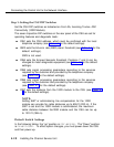
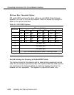
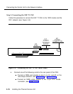
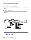
Step 3: Connecting the ESF T1 CSU
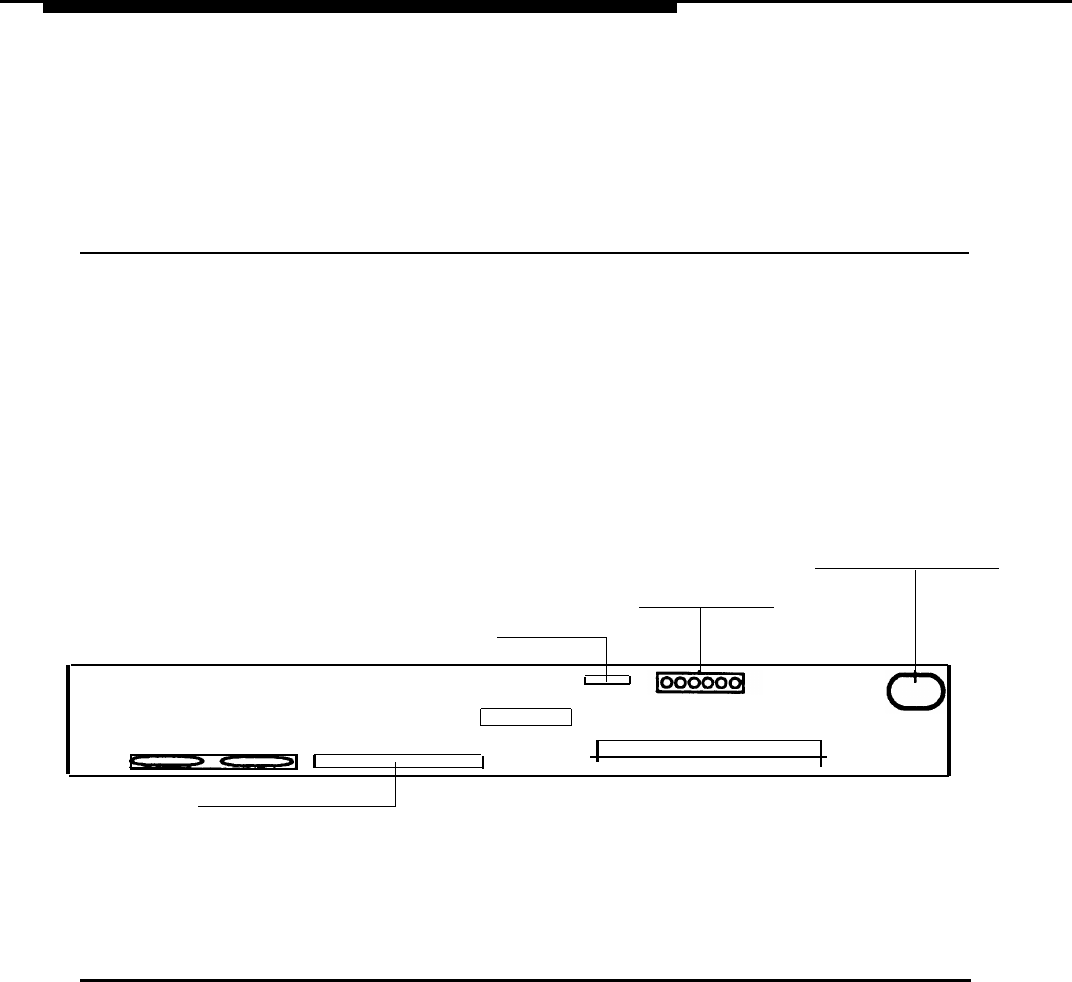
Follow this procedure to connect the ESF T1 CSU to the 100D module and the
DS1 network (see Figure 4-6):
DC
POWER
TERMINAL
AC
POWER
CONNECTION
DC
FUSE
BLOCK
DATA PORT
1
19
NET DTE
18
39
|
SW7
|
SW6
|
SW5
|
SW4
|
SW3
|
SW2
|
SW1
|
WIRE WRAP CONNECTOR
Figure 4-6. Connecting the ESF Tl CSU (Rear Panel)
a. Connect one of the following cords to the rear panel of the CSU:
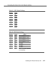
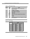
■ Connect a D8W cord directly to pins 3, 5, 21, and 23 on the
wire-wrap connector (see Table 4-14 and Table 4-15).
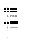
■ Connect an M4BJ cable adapter to the 15-pin DTE female
connector (see Table 4-16).
4-26
Installing the Channel Service Unit