


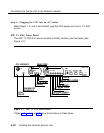
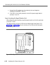
Connecting the Control Unit to the Network Interface
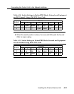
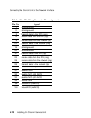
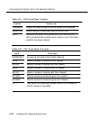
Table 4-18. CSU Front Panel LEDs
LED
Color
LOCAL POWER
Yellow
Network Side:
FAR END LOOPED
Red
CRITICAL PWR
Yellow
PULSES
Green
FRAME LOSS
Red
CRC ERROR
Red
BPV
Red
NEAR END LOOPED
Yellow
ALARM
Red
System Side:
LOOPED
Yellow
FRAME LOSS
Red
LOW DENS
Red
ACO
Yellow
When Lit Indicates
Local 117 VAC or -48 VDC is ON
Far-end CSU looped if initiated by near-end
CSU.
Power is on to critical circuits
Normal incoming signal from network
Loss of signal, loss of frame synch,
improper frame sequence, or unframed
signal
CRC error detected
Non-B8ZS violation detected when optioned
for B8ZS; other bipolar violations detected
Loopback is activated
BER threshold exceeded (associated
contacts for an audible alarm are also
activated)
Loopback activated on system side
Loss of signal, loss of frame synch,
improper frame sequence, or unframed
signal
Avg. ones density below threshold or
consecutive zeroes threshold
Lights when ACO button is pressed when
ALARM LED is lit
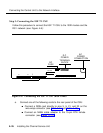
Installing the Channel Service Unit
4-31