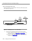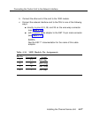
Connecting the Control Unit to the Network Interface
10-5
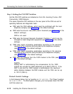
2 up up
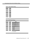
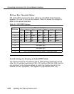
Bit-Error Rate Threshold Option
DIP switch SW2 can be set to alarm at bit-error rate (BER) threshold levels
between 10-4 and 10-9 or can be disabled. Table 4-9 shows the settings for
SW2 for the various thresholds.
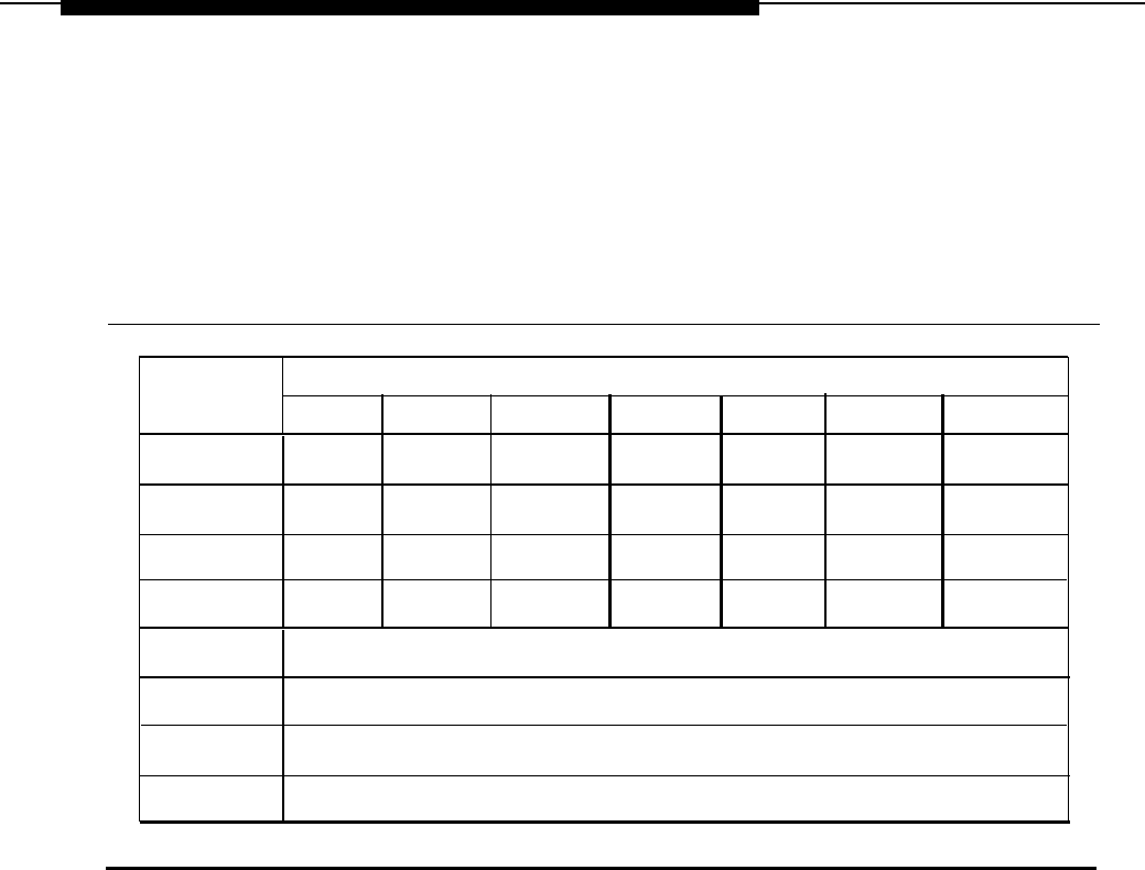
Table 4-9. SW2 BER Options
Threshold Option
Position
10-4
10-6
10-7
10-8
10-9
Disable
1
up down up
down up down
down
down
down
up
up up
3
up up
up
up
down
down
up
4
up up
up
up
up up
down
5
not used (up)
6
not used (up)
7
not used (up)
8
up
= non-latching mode; down = latching mode
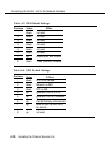
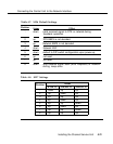
Switch Settings for Framing in Hybrid/PBX Mode
The framing format for the network and for data terminal equipment can be
either D4 or extended superframe (ESF). DIP switches SW5 and SW6 must be
set according to the following tables to match the framing format for the
network and the equipment. This applies to Hybrid/PBX mode only.
4-22
Installing the Channel Service Unit


