


Connecting the Control Unit to the Network Interface
Office Repeater Switch Settings
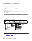
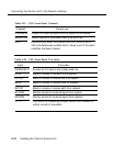
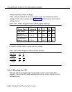
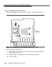
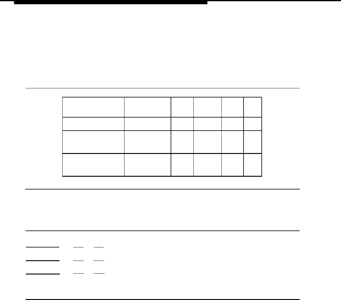
Table 4-22 and Table 4-23 show the power
settings for the office repeater. See Figure
mode and artificial line-option
4-11 for the location of the option-
setting screws.
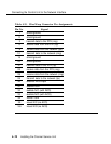
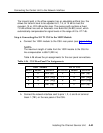
Table 4-22. Office Repeater Power Mode Option Settings
Screw
Power Mode
Options
✱
S2
S3
S4
S5
Line power
C, E, K
n/a n/a
AB
B
-48 V with
sealing current
C, E, K
Y OU
AA B
-48 V without
sealing current
C, G, J
Y
OUT
AA
B
✱ Letters indicate those screws that are closed.
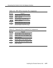
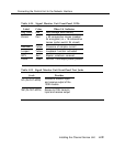
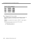
Table 4-23. Office Repeater Artificial Line Options
Line Loss S1 S5
0 dB C n/a
7.5 dB
A
A
15 dB B B
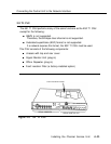
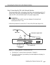
Step 2: Mounting the CSU
After the options have been set on the signal monitor unit and the office
repeater, mount the CSU shelf assembly into a relay rack, a cabinet, or as a
standalone unit.
4-36 Installing the Channel Service Unit