Connecting Data Equipment
4. If the modem pool is to be connected directly to the network interface,
skip this step.
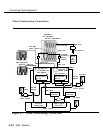
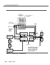
Connect the modem to the Logical ID as indicated on the appropriate
modem pool data form:
a. Connect one end of a D4BU cord to the
LINE
jack on the
modem.
b. Connect the other end to the appropriate logical ID on the
008 OPT or 012 module.
c. Skip Step 5.
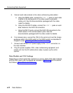
5. If the modem pool is to be connected directly to the network interface,
connect the modem to the outside trunk jack as indicated on the
appropriate modem pool data form:
a. Connect one end of a D4BU cord to the
LINE
jack on the
modem.
b. Connect the other end to the appropriate GS/LS outside trunk.
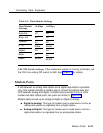
6. Set the options on the modem(s) and data module(s) as described in
the next section, “Option Settings.”
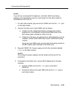
7. Plug the power cords of the WP90110-L7 power supply and modem
into an AC outlet that is not controlled by a wall switch.
NOTE:
If you are using the multi-mount arrangement, connect the power
supplies to AC as indicated in the 7500B data module
documentation.
6-28
Modem Pools


