Figures
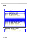
Figure 3-25. Using the D-Impact Tool to Seat the
Conductors
Figure 3-26. Routing the Wires through the Wire Troughs
and D-Rings
Figure 3-27. SYSTIMAX Hardware Kit (See also
Figure 3-22)
Figure 3-28. Attaching the SYSTIMAX Template to the Wall
Figure 3-29. Using the SYSTIMAX Template to Place the
Hardware
Figure 3-30. Drilling Holes for Each Piece of Hardware
Figure 3-31. Using the 788J1 Tool to Seat and Trim the
Conductors
Figure 3-32. Using the Reversed Blade Edge on the 788J1
Impact Tool
Figure 3-33. Connecting Termination Blocks to
Field-Terminated Blocks
Figure 3-34. Connecting Two Voice Pairs to a Telephone
Using a Bridge Adapter (BR-241-B1)
Figure 3-35. Pressing the Wires Over the Slots in the Outlet
Figure 3-36. Removing the Connecting Block
3-51
3-52
3-54
3-56
3-57
3-58
3-60
3-61
3-63
3-64
3-66
3-73
4
Connecting the Control Unit to the
Network Interface
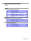
Figure 4-1.
RJ21X Network Interface Connector
Figure 4-2.
RJ21X Wiring Field Hardware
Figure 4-3.
RJ21X Wiring Field Tools
Figure 4-4. Using the D-Impact Tool to Seat the
Conductors
4-5
4-7
4-8
4-10
Contents
vii


