


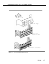
Connecting the Control Unit to the Network Interface
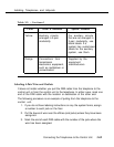
The adapter needed to connect the central office trunks to the control unit
depends on the type of network interface, as shown in Table 4-1.
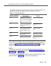
Table 4-1. Network Interfaces
Network Interface
RJ11
Description
Connects one outside
ground-start (GS), loop-start
(LS), or Direct Inward Dialing
(DID) trunk to one modular
jack
Adapter
RJ14
Connects two outside trunks
to one modular jack (GS, LS,
and DID)
RJ21X
RJ2GX
RJ48C/X
50-pin connector connects 25
110AB1 jack-panel block
outside trunks (GS, LS, and
DID)
50-pin connector for up to
eight tie trunks
Connects DS1 facilities to a
4-pair jack (two active pairs)
2-line adapter (267C-
type)
110AB1 jack-panel
block
356A eight tie trunks;
259A for one lie trunk
Z601A if modular cords
are used
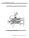
After installing the adapter, label each jack going to the control unit with the
central office trunk number. Use the list provided by the local telephone
company or System Form 2c, System Numbering—Trunk Jacks for outside
trunks as a reference.
NOTE:
If you need to connect the trunk cords differently from the instructions on
the system forms, record each change on Form 2c, System Numbering—
Trunk Jacks, See Appendix A.
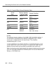
You may also need to know the interface codes for network facilities. These
codes are shown in Table 4-2 by trunk type and adapter type.
Wiring
4-3