


Installing Telephones and Adjuncts
8.
9.
10.
11.
12.
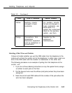
Using the diagonal pliers or wire strippers, cutoff the other end of the
patch cord and expose the pairs. Do not cut off too much of the cord
because you’ll need the length to test the top rows of the
cross-connect field.
The handset also has two clips with “teeth” that extend from its base.
Attach the clip of the handset to the exposed wires of the patch cord.
Set the switch on the side of the handset to MONITOR.
Listen in the handset for the tone device signal.
If you hear the signal, you,have found the correct wires. Correctly label
both the cross-connect field and the outlet.
If you don’t hear the signal, remove the patch cord from the connecting
block and push the patch cord down onto the connecting block to the
right of the one just tested. Keep moving the patch cord to the next
connector block on the right until you find the pairs that carry the tone
device signal.
Remove Damaged Connecting Blocks
In some cases, a connecting block can become damaged and must be
removed as follows.
1. Remove the wires or the patch cord from the connecting block.
■ With interconnect wiring, remove the telephone wires with
long-nosed pliers and tag the wires with tape to identify their
position.
■ With SYSTIMAX, pull off the patch cord.
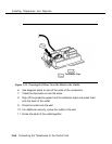
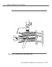
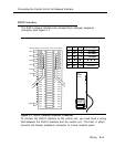
2. Place a 788K1 retainer tool against the conductor pairs beneath the
connecting block to be removed.
3. Grip the connecting block in the center with pliers. Move the block
gently up and down and pull it out. See Figure 3-36.
3-72 Connecting the Telephones to the Control Unit