Figures
2
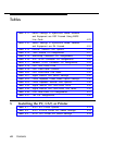
Installing the Control Unit
Figure 2-1.
AC Grounding Requirements
Figure 2-2.
Measuring the AC Outlet Voltages
Figure 2-3. Central Office and AC Grounds
Figure 2-4.
Installing 146A and 147A Protectors
Figure 2-5.
Marking the Basic Carrier Screw Holes
Figure 2-6.
Installing the Housing Clips on the Carrier
Figure 2-7. Removing the Control Unit Housing
Figure 2-8. Connecting the Carriers
Figure 2-9.
Installing a Ring Generator in the Power
Supply
Figure 2-10. Replacing a Ring Generator
Figure 2-11. Installing a Copper Shield in the Power Supply
Figure 2-12. Modifying the Processor Board for Key Mode
Figure 2-13. Installing the Feature Module in the Processor
Figure 2-14. Installing the Processor into the Carrier
Figure 2-15. Installing an Auxiliary Power Unit
Figure 2-16. Setting the 400EM Module DIP Switches for
E&M Signaling Types 1C and 5
Figure 2-17. Trunk and Telephone Jacks on Each Module
2-7
2-10
2-12
2-17
2-20
2-21
2-23
2-26
2-31
2-34
2-37
2-42
2-44
2-47
2-49
2-54
2-58
3
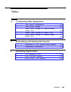
Installing Telephones and Adjuncts
Figure 3-1.
Multi-Function Module Packing List
3-3
Figure 3-2.
Remove Desk Stand and Module Cover
3-5
Figure 3-3.
MFM Locking Tabs
3-7
Figure 3-4. Setting the MFM Jumpers
3-8
Contents v


