


Installing Telephones and Adjuncts
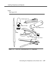
Tools
■ D-impact tool
■ 788J1 impact tool
■ spudger
■ hand tools
SYSTIMAX Wiring Procedure
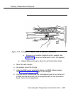
1.
2.
3.
Locate the proper wall space. The cross-connect field will usually be
to the right of the control unit. Leave enough space between the
control unit and the cross-connect field to allow for system growth.
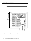
Attach the template to the wall or backboard with a staple gun, tacks,
or tape. Make sure that the upper edge of the template outline is 70
inches (177 cm) above the floor and that the template is parallel to the
floor.
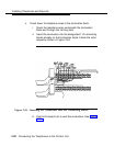
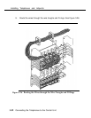
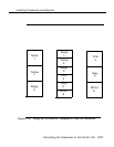
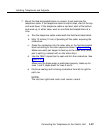
Find the placement of the hardware on the template. See Figure 3-29.
The first and third columns on the template show where the termination
blocks go; the middle
-
column shows the place for the field-terminated
blocks.
Keep the elements of a kit in the same-colored blocks. For example,
the termination blocks of kit #1 go in the green section of column 1; the
field-terminated block of kit #1 goes in the green section of column 2.
Connecting the Telephones to the Control Unit
3-55