


Installing the Control Unit
5.
6.
7.
8.
9.
10.
11.
12.
Disconnect the expansion carrier connector from the previously
mounted carrier and put the expansion carrier aside.
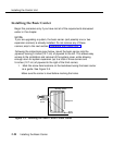
Drill a pilot hole in the center of each of the four screw-hole marks.
Anchor the screws approximately halfway into the backboard.
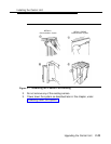
If this is the last carrier in the system, place the control unit housing
clips around the right-hand molding for the screws on the back of the
carrier.
If not, skip this step.
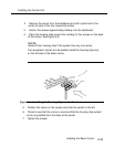
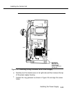
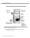
Position the expansion carrier on the screws and slide it to the left,
thereby reconnecting the expansion carrier card extender to the
previous carrier’s connector.
Make sure the connection is secure.
Check to see that the carrier is level and that the housing clips extend
as far as possible from the right side of the carrier.
Tighten the screws.
Installing Expansion Carriers
2-27