


Connecting the Control Unit to the Network Interface
Installing the 551 T1 CSU involves the following:
1. Setting the CSU DIP switches
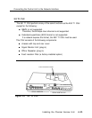
2. Mounting the CSU in a relay rack or on a shelf as a stand-alone unit
3. Connecting the CSU to the network interface
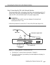
4. Inserting the signal monitor unit
5. Inserting the office repeater
6. Connecting the CSU to the 100D module
7. Plugging the CSU into an outlet
NOTE:
Before the CSU can be installed, the serving telephone company must be
contacted to obtain all necessary information, such as services available,
equipment options, and power on the line.
These steps are explained in detail in the sections that follow.
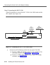
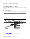
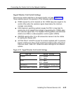
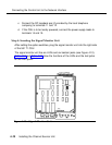
Step 1: Setting the CSU DIP Switches
Before placing the signal monitor unit and the office repeater in the CSU, set
the CSU DIP switches according to the specifications on Form 3b, Incoming
Trunks—DS1 Connectivity (100D Module).
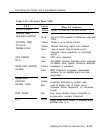
The default settings accommodate most installations. However, some options
depend upon local line conditions, for example, availability of line power and
the type of service requested by the customer.
Also, proper settings for some options must be obtained from your technical
support organization, the customer’s authorized dealer, or the local telephone
company. The local telephone company representative must be informed of
the options selected.
4-34
Installing the Channel Service Unit