


Installing Telephones and Adjuncts
Hardware
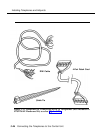
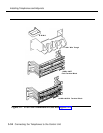
Each kit includes the following:
■ instructions and parts sheet
■ 110AB1-100JP12 termination blocks with modular jacks
■ 110A1 wire troughs
■ D-rings
■ D8W cords
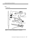
Tools
■ D-impact tool
■ spudger
■ hand tools
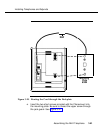
See Figure 3-23.
Telephone Installation Procedure (More than 24)
1.
2.
3.
4.
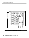
Drill two diagonally opposite holes in a suitable backboard (plywood is
recommended) for each piece of hardware. Keep a 1/16-inch (1.6-
mm) space between each piece of hardware.
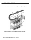
Mount the wire troughs and the termination blocks. There is a wire
trough above each termination block.
If necessary, repeat Steps 1 and 2 for a second column.
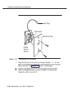
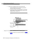
Mount the termination blocks and terminate the telephone cable. If the
telephone cable is bottom feed, start at the top and work down. If the
telephone cable is top feed, start at the bottom and work up.
a. Mount a termination block to the wall with appropriate fasteners.
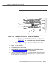
b. Strip the jacket off the DIW telephone wires, exposing the
conductors.
Connecting the Telephones to the Control Unit
3-49