


Installing the Control Unit
.
g.
h.
i.
j.
k.
l.
m.
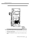
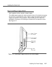
NOTE:
Make sure the
P1
header on the ring generator is on the same side
of the power supply housing as the
P101
header on the circuit
board.
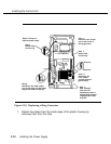
Secure the ring generator using the four screws, one in each corner.
Connect one end of the ring generator’s cable with the 3-pin
connectors to the header labeled
P101
on the power supply circuit
board.
NOTE:
This cable connector, as with all four cable connectors, is “keyed”
so that you cannot attach it to the header if it is turned the wrong
way.
Connect the other end of the cable to the header labeled
P1
on the
ring generator.
NOTE:
The cable headers,
P1
and
P101,
should be on the same side of
the housing, so that the cables do not cross each other.
Connect one end of the 4-pin cable to the header labeled
P202
on the
power supply circuit board.
Connect the other end of the cable to the header labeled
P2
on the
ring generator.
Use the clips provided with the ring generator to attach the cables to
the inside edge of the plastic housing.
Replace the top of the module housing.
2-32
Installing the Power Supply