


Connecting Data Equipment
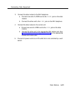
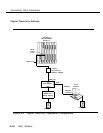
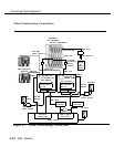
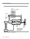
5. Connect each data module to the video conferencing data station:
a. Using the DB25 cords, connect the PORT 2 jacks on each data
module to the dialing ports in the video codec’s automatic
calling unit. See the documentation packaged with the video
codec for details.
b. Using the EIA-232-D cables, connect the
PORT 1
jacks on each
data module to the EIA/V.35 converters.
c. Using the DB-37 cords, connect the EIA/V.35 converters to the
video codec’s V.35 communication ports. See the
documentation packaged with the video codec for details.
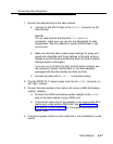
6. If not already done, connect the CSU to the control unit and the foreign
exchange switch (the 4ESS switch or the 5ESS switch) as described in
Chapter 4 under “Installing the Channel Service Unit.”
7. Connect each WP90110-L7 power supply to the
POWER
connectors on
the data modules.
8. Plug the power supplies, CSU, video conferencing equipment, and
control unit into the AC outlets when ready to power up the entire
system.
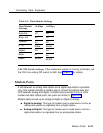
Data Module and CSU Settings
Depending on which speed the customer is running, both of the data modules
and the CSU need to be configured as indicated in Table 6-2 and the section
that follows, “CSU DIP Switch Settings.”
6-22
Data Stations