


Connecting the Control Unit to the Network Interface
The transmit path in the office repeater has an adjustable artificial line; this
allows the transmit level to be adjusted to 0, 7.5, or 15 dB to meet the
required -15 or -22.5 dB section loss. The receive path contains a fixed
7.5 dB artificial line and an Automatic Line Build-Out (ALBO) circuit, which
automatically compensates for signal levels in the range of 0 to -27.7 db.
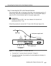
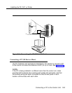
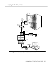
Step 6: Connecting the 551 T1 CSU to the 100D Module
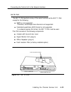
a. Connect the 100D module to the CSU rear panel (see Figure 4-9).
NOTE:
The maximum length of cable from the 100D module to the CSU for
line compensation is 655 ft (200 m).
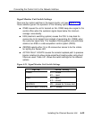
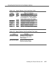
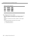
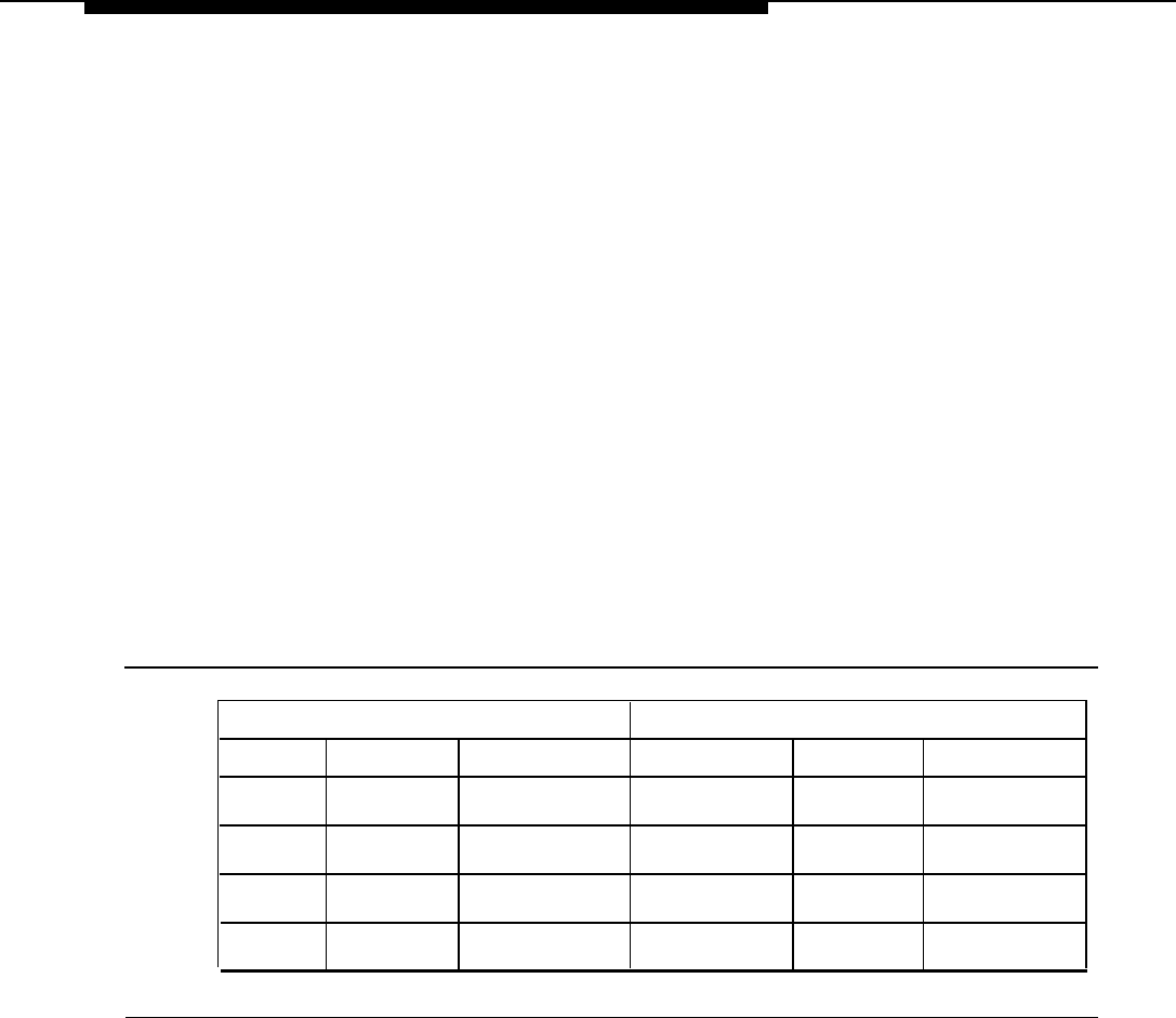
Table 4-26 shows the pin assignments for the rear panel connections.
Table 4-26. CSU Rear-Panel Pin Assignments
100D Module
551 T1 CSU
PIN #
DESIG SIGNAL
D-CONN
DESIG
SIGNAL
1
T1
RCV (tip)
3
T
XMT (tip)
2
R1
RCV (ring)
11
R
XMT (ring)
4 R
XMT (ring)
9
R1
RCV (ring)
5
T
XMT (tip)
1
T1 RCV (tip)
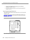
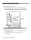
b. Connect the network interface cord to pins 1, 2, 4, and 5 on terminal
block 1 (TB1) on the rear panel of the CSU.
Installing the Channel Service Unit
4-41