


Installing the Control Unit
NOTE:
n.
o.
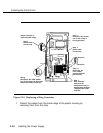
Take time to ensure that the on/off faceplate on the front of the
power supply housing is aligned and inside the top cover.
Carefully, taking time to make sure the on/off faceplate stays aligned,
turn the module over and replace the five screws on the housing.
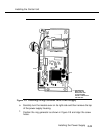
Fasten the modification label
Equipped with 129B Freq Gen
to
the wire manager (on the front of the power supply as shown in
Figure 2-9).
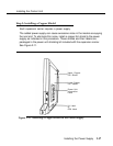
Step 2b: Replacing a Ring Generator
WARNING:
Hazardous electrical voltages may be present if the following steps
are not performed correctiy.
Follow these steps to replace a ring generator (see Figure 2-10 throughout
this procedure):
a. Make sure each power supply is turned off, including the module in the
control unit and any auxiliary power units.
b. Unplug the power supply cord from the AC outlet (or from the auxiliary
power unit) and then from the power supply,
NOTE:
At this point, all cords should be removed from the power supply.
c. Remove the power supply from the carrier.
d. Place the power supply on its left side and remove the five screws.
e. Carefully turn the module over on its right side and then remove the top
of the power supply housing.
Installing the Power Supply
2-33