


Installing
the
Control Unit
n.
o.
p.
q.
r.
s.
t.
u.
v.
w.
Connect the other end of the cable to the header labeled
P1
on the
ring generator.
NOTE:
The cable headers,
P1
and
P101,
should be on the same side of
the housing, so that the cables are not crossing each other.
Connect one end of the new 4-pin cable to the header labeled
P202
on
the power supply circuit board.
Connect the other end of the cable to the header labeled
P2
on the
ring generator.
Attach the cables to the clips on the inside edge of the plastic housing.
Replace the top of the module housing.
NOTE:
Take time to ensure that the on/off faceplate on the front of the
power supply housing is aligned and inside the top cover.
Carefully, taking time to make sure the on/off faceplate stays aligned,
turn the module over and replace the five screws.
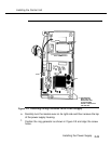
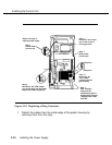
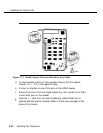
Verify that the modification label
Equipped with 129B Freq Gen
is
adhered to the wire manager (on the front of the power supply shown in
Figure 2-10).
If not, adhere the label supplied with the new ring generator.
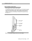
Reinstall the power supply by hooking the top into the carrier and then
swinging it down into place. Push the lower end firmly until the locking
tab clicks.
Reconnect the cords to the power supply and then the auxiliary power
units (if any were connected before).
Connect the cord(s) to AC power when ready to power up the system.
2-36
Installing the Power Supply