


Installing the Control Unit
Installing the Basic Carrier
Begin this procedure only if you have met all of the requirements discussed
earlier in this chapter.
NOTE:
If you are upgrading a system, the basic carrier (and possibly one or two
expansion carriers) is already installed. Do not remove any of these
carriers; skip to the next section, “Upgrading the Control Unit.”
Following the instructions given below, mount the basic carrier onto the
plywood, leaving 5 inches (12.7 cm) of plywood to the left. This allows easy
access to the installation and removal of the system cover, while allowing
enough room for system expansion (up to a total of three carriers and
5 inches (12.7 cm) of plywood to the right of the third carrier).
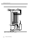
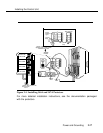
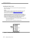
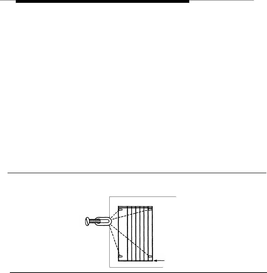
1. Mark the screw hole locations on the backboard using the basic carrier
as a guide. See Figure 2-5.
Make sure the carrier is level before marking the holes.
Mounting Surface
Mounting
Screw
Background
Basic
Carrier
Figure 2-5. Marking the Basic Carrier Screw Holes
2-20
Installing the Basic Carrier