


INSTALLATION-CONFIGURATION
SECTION 200-096-204
FEBRUARY1991
DK24 (PCTUS)
I
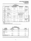
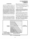
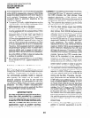
CO Lines
16
16
16 16
12 24
12 24
8
24
8 32
4 24
4 323
0
24
0 323
Stations
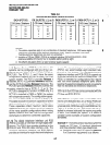
Table 4-A
OK24/56/96 MAXIMUM CONFIGURATIONS
DK 24 (PCTU 1,2. or 31 DK56 (PCTU 1.2. or :
I I
CO Lines Stations
.
CO Lines
, ,
Stations
20
24
16 32
12 40
8 48
4
56
0 64
DK96 (PC-
CO Line5
36
32
28
24
20
16
12
8
1, 2, or:
Stations
NOTES:
1. The station capacities apply to any combination of standard telephones, IOOO-series digital
telephones and 6500-series electronic telephones (only). Station capacities using other
Toshiba electronic telephones are given on worksheet 7.
2. Installing a TIE line (PEMU) PCB or an optional interface (PIOU/PIOUS/PEPU) PCB
reduces available CO lines by four or available station ports by eight.
3. The DK24’s 32-station limit is a result of power supply capacity.
40
48
56
64
72
80
88
96
1 .13 System Control PCB Considerations. DK
systems can be configured with one of four ver-
I
sions of control PCBs: PCTUl , PCTU2, PCTU3, or
PCTUSI. The PCTUl, 2, and 3 have the same
configuration capacity and can be used in all three
system models. The PCTUI provides Release 1
I
features; the PCTU2 provides Release 2 features;
and the PCTU3 provides Release 3 features. The
PCTUSl provides Release 2features, but has less
I system capacity than a PCTU (1, 2, or 3). The
PCTUS is designed to function in DK24 only; if a
PCTUS is installed in DK56 or DK96, the system
will not operate correctly. The configuration capaci-
ties of each PCTU PCB are shown in Table 4-B.
This table shows the maximum capacities of all the
options, stations, and lines for each configuration.
These capacities reflect maximum stand alone
capacities and do not indicate combined capacity
of the many possible configurations when mixing
options, stations, and lines. Use the configuration
worksheets to determine combined capacities.
I
1.14 The digital telephone interface unit PCB
(PDKU) provides an interface for eight digital tele-
phones. The PDKU also provides interface for the
PDIU-DI and PDIU-DS data interface units. The
electronic telephone interface unit PCB (PEKU)
provides an interface for eight electronic telephone
circuits. The standard telephone interface unit PCB
(PSTU) can accommodate eight standard tele-
phones or like devices. The standard/electronic
telephone interface unit PCB (PESU) supports up
to two standard and four electronic telephones. The
PESU is intended for configurations that require
less than three standard telephone ports and/or
less than five electronic telephone ports, on systems
that mix standard and electronic telephones.
1.15 Up to four CO lines can be connected with the
CO line unit PCB (PCOU).
1 .16 With the exception of the control PCB which
has its own dedicated slot, any of these PCBs can
be used in any of the universal slots (DK24 has six
universal slots, DK56 has eight, and DK96 has 14).
Table 4-C shows all the PCBs which can be in-
stalled in universal slots and the maximum quantity
of each PCB allowed per system. It is useful to
consider some examples of system configuration
as follows:
Example 1-A small business requires a system to
handle six CO lines, 12 electronic telephones
and three standard rotary type telephones.
l
The PCBconfiguration (in addition to Release
1 or 2 common equipment) is as follows:
4-2